What is a Resistance Temperature Detector (RTD) – Pt100?
There are three main types of temperature sensors: thermocouples, thermistors, and RTDs. RTD stands for Resistance Temperature Detector, which means that temperature is measured using a property that metals have. They change their electrical resistance depending on the temperature. For an RTD to work, it requires a current source and must be mounted on an ohmmeter.
Because it is stable, platinum is the most common material used to build an RTD temperature probe. It is its chemical symbol, Pt, which is found in the terminology of the probe. The nominal resistance of platinum at 0 °C can vary, for example, 100 Ω, 200 Ω, 500 Ω or 1000 Ω. Pt100 sensor means it is made of platinum with a resistance of 100 Ω at 0 °C.
An RTD temperature sensor will be optimal when the temperature is relatively stable and the user wants good accuracy (measurement fidelity).
How to quickly get ready-to-use measurements from RTD-PT100 sensors with Dracal
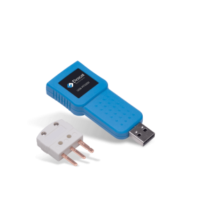
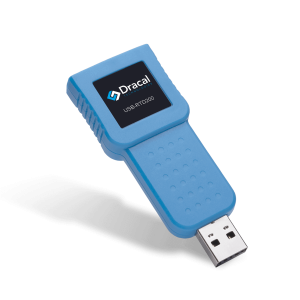
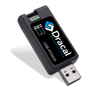
If you don’t yet have an established solution for integrating your RTD sensors into your system, Dracal Technologies offers a series of USB-connected transmitters that give you instant access to ready-to-use measurements from the RTD-PT100 probe of your choice:
These precision instruments not only allow you to view and log your data in just 3 minutes, thanks to the free and multi-platform DracalView software, they also give you the option of integrating the data into your existing system, with their free and intuitive integration tools. Ready-to-use code examples and LabVIEW integration examples will help you turn your RTD sensor data integration into a successfully completed project faster than you can imagine.
Standards for Pt100 probes
 To ensure uniformity in Pt100 sensors, the International Electrotechnical Commission has issued the IEC 60751 standard.
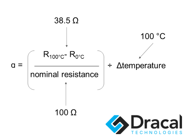
Several aspects are part of this standard. The first is the temperature coefficient, also called the ɑ coefficient. This coefficient is used to determine the quality of the platinum that is used to build a probe to standards. For example, with a Pt100 probe, we know that the resistance of the platinum at 0 °C is 100 Ω. Therefore, to use platinum that will perform to IEC 60751, the resistance at 100 °C must be 138.50 Ω.
Thus, the platinum used in IEC 60751 must have a ɑ coefficient of 0.00385 Ω/Ω/°C.
In the United States, the standard used is ASTM E-1137. Therefore, the temperature coefficient according to the U.S. standard is slightly different (0.003902 Ω/Ω/°C) from that of IEC 60751.
The second aspect of this IEC 60751 standard is the tolerance curve of a Pt100 RTD probe. The tolerance curve correlates resistance to temperature with a defined accuracy that varies with temperature.
In the past, two European associations had established tables that predicted the resistance change behaviour as a function of the temperature of a “standard” probe: the British Standards Association and the Fachnormenausschuß Elektrotechnik im Deutschen Normenausschuß. In addition, the German association had created the DIN 43760 standard, where the tolerance curve defined there (in table form) is essentially the one that was retained when the IEC was made.
Another entity, the International Temperature Standard 90 (ITS-90), uses the Callendar-Van Dusen equation to define the relationship between the temperature and resistance of a Pt100 probe. This equation consists of two parts: a degree 3 equation for temperatures below 0°C and a degree 2 equation for temperatures above 0°C. The Callendar-Van Dusen equation includes constants A, B, and C, which are derived from the parameters ɑ, β, δ using resistance measurements at three defined temperatures, 0°C, 100°C, and 260°C.
Since the 2022 update to IEC 60751, the relationship between temperature and resistance must be calculated using the polynomial equations defined by ITS-90. Today, the tolerance curves of a Pt100 RTD probe are specified in IEC 60751 or DIN EN 60751. Several tolerance classes exist for Pt100 probes, such as Class A and Class B. Depending on the construction and the class, the behavior of the RTD probe at different temperatures may vary.
Pt100 RTD probe classes
The RTD probe classes determine the accuracy of the Pt100 probe at different temperatures and the temperature range for which this accuracy is valid. These are called tolerance classes.
In the IEC classes, there is now a distinction between thin-film and wire RTD probes regarding the temperature range where the accuracy is valid. This accuracy is called tolerance.
The other aspect of the update of the IEC standard is that the tolerance classes are now established according to whether the validity must be on the whole thermometer or only the resistive element.
Here are the classes for RTD thermometers.
Wire resistor element
Classs |
Intervalle de validité (°C) |
|---|---|
AA |
-50 to 250 |
A |
-100 to 450 |
B |
-196 to 600 |
C |
-196 to 600 |
Thin-film resistor element
Classs |
Intervalle de validité (°C) |
Tolérance de la classe (°C) |
|---|---|---|
AA |
-50 to 250 |
± (0.1 + 0.0017t) |
A |
-100 to 450 |
± (0.15 + 0.002t) |
B |
-196 to 600 |
± (0.3 + 0.005t) |
C |
-196 to 600 |
± (0.6 + 0.01t) |
t: temperature
Class B has another name: DIN. With this other terminology, we understand that “the” usual tolerance curve was once that of class B. When using the DIN terminology, it is common to find class names that are fractions of the standard DIN tolerance. The most common are 1/3 DIN, 1/5 DIN, and 1/10 DIN. Only the 1/3 DIN class has been standardized with IEC 60751. It is the AA class.
Why is it called 1/3 DIN? Because its tolerance is ⅓ of the “DIN” class tolerance. This implies that the accuracy of this probe, within its validity interval, will be very high. This is the type of RTD probe we offer at Dracal.
The 1/10 DIN class has a tolerance of ± (0.03 + 0.0005t) for extreme accuracy. However, its operating temperature range is more restricted.
Electronics of an RTD sensor
As mentioned in the introduction, for an RTD sensor to return a temperature, the resistive element must be connected to a current source using insulated metal wires. There must also be an ohmmeter in the circuit. When discussing a Pt100 sensor, remember that the resistive element is platinum with a resistance of 100 ohms at 0°C.
2-wire RTD sensor
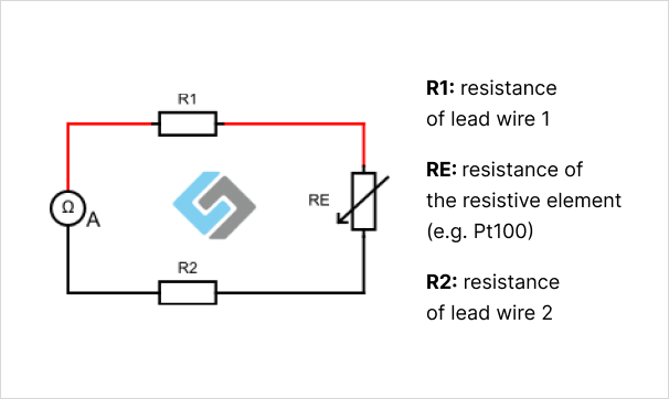
There are several possible configurations for the electrical circuit of an RTD sensor. The primary circuit comprises two wires connected to the resistive element and an ohmmeter.
The resistance measured by the ohmmeter A is, therefore, R1+RE+R2. With a 2-wire RTD sensor, it is necessary to have a calibration table to subtract the resistance of the wires. This table must be updated each time the temperature conditions change.
3-wire RTD sensor
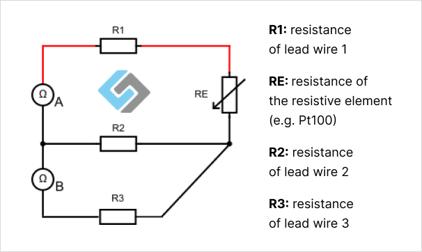
More commonly, there are 3-wire RTD probes. They allow to compensate for the resistance of the wires and therefore offer a more accurate temperature measurement.
Here is how the Pt100 element (RE) resistance is calculated using a 3-wire probe.
Ohmmeter A measures: R1+RE+R2
Ohmmeter B measures: R2+R3
If R1=R2=R3, (three identical wires, assumed to be at the same temperature)
Then, Ohmmeter A – Ohmmeter B = RE
This is why the 3-wire RTD probe is more robust than a 2-wire RTD probe: no need for a calibration table; the system allows the calculation of the resistance of the platinum element only. There is, therefore, less possible measurement error.
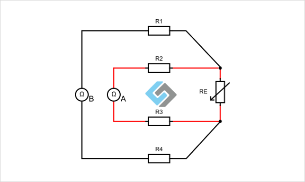
4-wire RTD sensor
There is another version of the electrical circuit of an RTD sensor: the 4-wire version. This sensor is more accurate and robust but also more expensive. It is, therefore, not necessarily recommended when the wires must be very long.
The illustration above shows that there is compensation for each of the wires. Here, it is no longer necessary to stipulate that the wires are at the same temperature since R2 and R3 will be cancelled out by R1 and R4, leaving only RE.
Temperature calculation from a Pt100 RTD sensor
It is recommended to send about 1 mA of current to the electrical circuit of an RTD sensor. Then, regardless of the construction (2, 3, or 4 wires), the resistance of the platinum element will be calculated using ohmmeters. With the Callendar-Van Dusen equations mentioned above, it is possible to find the temperature associated with the resistance measurement of a Pt100 RTD sensor.
Conclusion
An RTD temperature sensor is an electrical circuit where the resistance element is used to measure temperature since the electrical resistance of a metal changes with temperature. In the case of a Pt100 RTD sensor, the resistance element is made of platinum, whose resistance at 0°C is 100 Ω. For this probe to meet international standards IEC 60751, its temperature coefficient must be 0.00385 Ω/Ω/°C, and its tolerance must be in one of 4 standardized classes, either AA, A, B, or C. Each of these classes is defined by a tolerance curve, where the accuracy of the probe and the validity range of that accuracy are standardized.
The platinum resistance element can be part of a 2, 3, or 4-wire circuit. The most common construction is the 3-wire circuit since it compensates for the resistance of the wires and, therefore, allows for better measurement accuracy while not being too expensive. The temperature is then calculated using the Callendar-Van Dusen equation, which correlates the resistance and temperature of a platinum probe with a ɑ coefficient of 0.00385 Ω/Ω/°C.
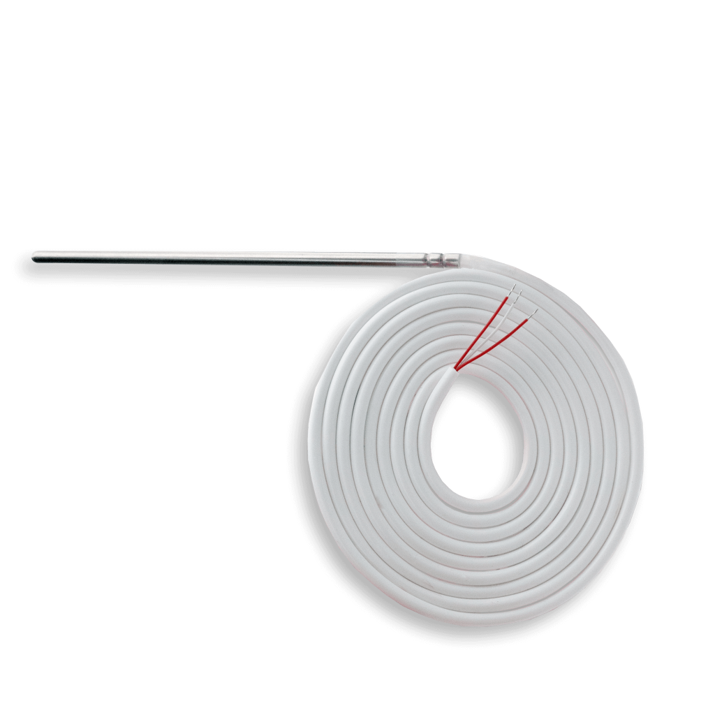
The Dracal Technologies RTD-PT100-SIL probe is a 3-wire Class AA (or 1/3 DIN) RTD sensor, providing excellent accuracy and wire resistance compensation. It uses IEC 60751-compliant platinum. The sensor can be connected to a suitable converter to obtain a quick temperature reading. This converter calculates the temperature using the Callendar-Van Dusen equation if it follows the ITS-90 or IEC 60751 standards.
Dracal Technologies’ USB converters (RTD223, RTD200, and RTD300) are compatible with 2 or 3-wire RTD Pt100 probes, regardless of their IEC class, allowing you to use the probe with the accuracy you need instantly.
PRODUCTS YOU CAN TRUST
Approved by engineers, scientists and researchers around the world.
Thousands of companies trust our products worldwide:


Get ready-to-use measurements from RTD-PT100 sensors with Dracal
Always offered at no extra charge with our products!
EASY TO USE IN YOUR OWN SYSTEM
- Ready-to-use, accurate and robust real-time data flow
- Choose the interface that works best for you (CLI, virtual COM, REST API)
- Code samples available in 10+ programming languages (Python, C/C++, C#, Java, Node, .Net, etc.)
- Operates under Windows, Mac OS X and Linux
- Usable with LabView (CLI guide, Virtual COM guide)
- All tools packaged within one simple, free of charge, DracalView download
FREE DATA VISUALIZATION, LOGGING AND CALIBRATION SOFTWARE
- Get up-and-running in less than 3 minutes
- Operates under Windows, Mac OS X and Linux
- Real-time on-screen graphing and logging
- Log interval down to 0.5 second and configurable units (°C, °F, K…)
- Simultaneous use of unlimited Dracal sensors supported
- Simple user-calibration (products with the -CAL option)
- Connectivity with SensGate Wi-Fi/Ethernet gateway

Not sure if your project will benefit from Dracal’s solution?
Contact us, tell us about your project, and we’ll quickly determine if there’s a fit.
"*" indicates required fields
References
iqsdirectory.com. (n.d.) RTD Sensor: What Is It? How Does It Work? Types, Uses. [online] Available at: https://www.iqsdirectory.com/articles/thermocouple/rtd-sensors.html [Accessed 23 Jan. 2023].
Omega.ca. (2021). What is the Difference Between a 2, 3, and 4 Wire RTD? [online] Available at: https://www.omega.ca/en/resources/rtd-2-3-4-wire-connections [Accessed 23 Jan. 2023].
Sachs, R. (2020). Pt100 in class B or F 0.3 according to IEC 60751. [online] WIKA blog. Available at: https://blog.wika.com/knowhow/pt100-in-class-b-oder-f-03-what-does-iec-60751-say [Accessed 23 Jan. 2023].
Senmatic.com. (2022). IEC 60751:2022 – the main points and updated tolerance classes. [online] Available at: https://www.senmatic.com/sensors/knowledge/iec-60751-sensor-tolerance-classes [Accessed 23 Jan. 2023].
TE Connectivity. (2022). Understanding RTDs. [online] Available at: https://www.te.com/usa-en/industries/sensor-solutions/insights/understanding-rtds.html [Accessed 23 Jan. 2023].