Documentation of the VCP (Virtual COM Port) option
[Last Update: 06/12/2023]
![]()
- 1. Introduction
- 2. Prerequesites
- 3. VCP products and DracalView
- 4. Conversion from USB mode to VCP mode
- 5. VCP mode: Requirements and data
- 6. Available commands in VCP mode
1. Introduction
Dracal sensors with the ability to communicate as virtual COM ports are identifiable by the prefix "VCP-" present in their product code. The communication protocol of these products can be freely converted between two modes: USB mode and VCP mode. Upon delivery, you will receive your VCP products in USB mode in order to allow a first quick overview of the data via our free data logging and visualization software DracalView. In this documentation you will find information about the conversion between USB and VCP communication modes, the format of the generated data as well as the commands available in VCP mode.
This documentation is intended for users who have the knowledge to manipulate the data generated by virtual COM port autonomously.
2. Prerequesites
1. Have installed DracalView (special instructions for users under Linux)
2. Have skimmed the Getting Started with Command-line Tools guide
3. Have skimmed the Getting Started with VCP mode guide
3. VCP products and DracalView
Dracal's VCP products that are in USB mode behave exactly like any classical Dracal USB sensor. Their data can be accessed via our command line tool dracal-usb-get or our free data logging and visualization software DracalView. However, once the communication mode has been changed to VCP mode, users working under Windows will no longer be able to access their data via these two tools. However, users working under Linux or Mac OS X will still be able to access their data via these two tools, due to the greater flexibility in the device management process of these two operating systems.
4. Conversion from USB to VCP mode
The communication protocol of VCP- series products is changed from USB mode to VCP mode via our command line tool dracal-usb-set. To do this, the conversion command set_protocol VCP must first be executed, and then be followed by the sensor disconnection. In the following example, and for all this documentation, we will use a VCP-PTH200 sensor whose serial number is E16026 to illustrate our point. Here, the disconnection of the sensor has been done virtually using the reset command available with dracal-usb-set:
C:Program Files (x86)DracalView>  dracal-usb-set -s E16026 set_protocol VCP
C:Program Files (x86)DracalView>  dracal-usb-set -s E16026 reset
If only one Dracal sensor is connected to your computer when executing these commands, you can omit to specify the serial number of your device (as there is only one) by using the option -f as in the following example:
C:Program Files (x86)DracalView>  dracal-usb-set -f set_protocol VCP
C:Program Files (x86)DracalView>  dracal-usb-set -f reset
Note for Windows users: When executing the command reset, the following echo will be returned in your terminal:
C:Program Files (x86)DracalView>  dracal-usb-set -f reset
USB control message error: usb_control_msg: sending control message failed, win error: The device does not recognize the command.
This behaviour is normal and confirms that the disconnection was successfully completed.
5. VCP mode: Requirements and data
5.1. Setting up your working tool
In order to allow sending commands to your Dracal device now in VCP mode, it is necessary to disable the echo of your data access tool, whatever it is (Linux terminal, Putty, etc.)
Also, we remind Linux users of the importance of having the necessary access rights to access the data. For more information, see point 5) of the documentation for Linux users.
5.2. Available data
Only the data from the real channels of your sensors are communicated by VCP protocol. Recall that a real channel is a channel whose data come directly from the reading of a physical quantity (temperature, relative humidity, pressure, concentration, etc.) while a virtual channel is one whose data are calculated from the real channels (humidex, altitude, etc.) To find out the nature (real or virtual) of the existing channels for your product, consult the "Available channels" section of the Specifications tab in its product sheet.
5.3. Data format
The format of the data generated in VCP mode by Dracal products is as follows (without the spacing):
where
- LINE_TYPE : The type of the line. The possible options are:
D: Data lineI: Information lineC: Calibrated data (for VCP products supporting Dracal calibration)
- PRODUCT : Product number (e.g.
VCP-PTH200) - SERIAL : Unique serial number of the product (e.g.
E16026) - MESSAGE : Echo message when a command is sent to the device (ex.
Poll interval set to 1000 ms) - (D1,U1),(D2,U2),...,(Dn,Un) : Readings in pairs (numerical value, unit) (e.g.
100676,Pa,23.8945,C.21.7853,%) - CHECKSUM : *[4-character hexa code calculated with CRC-16 function] (e.g.
*A13D)
The CRC algorithm is CRC-16-CCITT (XMODEM) and it is calculated for each line from the first character of the line up until the asterisk '*' exclusively, meaning the asterisk itself is not included. There is always exactly one asterisk per line, followed by the CRC expressed in 4 hexadecimal digits, followed by carriage return '\r' and newline '\n' . None of these characters are included in CRC computation.
Here is an excerpt of our VCP-PTH200 readings:
D,VCP-PTH200,E16026,,100681,Pa,*040A
%,D,VCP-PTH200,E16026,,100680,Pa,23.9239,C,23.154,%,*CC78
D,VCP-PTH200,E16026,,100680,Pa,23.9532,C,23.1098,%,*aa99
D,VCP-PTH200,E16026,,100684,Pa,23.9666,C,23.035,%,*723f
D,VCP-PTH200,E16026,,100680,Pa,23.9666,C,22.9892,%,*9758
D,VCP-PTH200,E16026,,100681,Pa,23.9666,C,22.9587,%,*8abb
D,VCP-PTH200,E16026,,100680,Pa,23.9372,C,23.0625,%,*1169
D,VCP-PTH200,E16026,,100681,Pa,23.9532,C,23.1098,%,*ef2d
D,VCP-PTH200,E16026,,100683,Pa,23.9532,C,22.9725,%,*01f3
Note: Remark that the first two reading lines may be incomplete or inconsistent. This is normal as it is very unlikely that the beginning of the user's data reading is exactly synchronized with the beginning of a communicated data line.
6. Available commands in VCP mode
6.1. Get information about columns: INFO command
The command INFO displays the description of the different data columns, which are specific to each sensor. This command allows, among other things, users who want to record data in a .csv file to get the header of their columns. Here is the result of the call of this command for our VCP-PTH200:
D,VCP-PTH200,E16026,,100724,Pa,22.2816,C,22.5376,%,*aa91
D,VCP-PTH200,E16026,,100724,Pa,22.3243,C,22.4674,%,*4e1d
D,VCP-PTH200,E16026,,100724,Pa,22.3083,C,22.3728,%,*8202
I,Product ID,Serial Number,Message,MS5611 Pressure,Pa,SHT31 Temperature,C,SHT31 Relative Humidity,%,*bbdd (Invoking command: INFO)
D,VCP-PTH200,E16026,,100725,Pa,22.3243,C,22.3301,%,*8a7d
D,VCP-PTH200,E16026,,100724,Pa,22.3377,C,22.3484,%,*0f44
D,VCP-PTH200,E16026,,100723,Pa,22.351,C,22.3026,%,*97d4
As the terminal is configured without echo, the invocation of the command INFO does not appear in the terminal while the result is present. Note, on the line corresponding to the result of the command, that the first character displayed is I, reminding that the line is not a data line, but an information line.
6.2. Set the data polling rate: POLL command
The command POLL n, n ≥ 0, is invoked to set to n (in ms) the data polling rate. Here is an illustration of the feedback displayed after the invocation of the command POLL 2000 (poll data every 2000 ms):
D,VCP-PTH200,E16026,,100696,Pa,23.3845,C,20.2197,%,*78df
D,VCP-PTH200,E16026,,100700,Pa,23.3711,C,20.3082,%,*25c8
D,VCP-PTH200,E16026,,100698,Pa,23.4005,C,20.3845,%,*3cac
D,VCP-PTH200,E16026,,100698,Pa,23.4005,C,20.4593,%,*6d48
I,VCP-PTH200,E16026,Poll interval set to 2000 ms,,,,,,,*b754 (Invoking command: POLL 2000)
D,VCP-PTH200,E16026,,100699,Pa,23.3845,C,20.5051,%,*4d46
D,VCP-PTH200,E16026,,100698,Pa,23.3711,C,20.4303,%,*01db
If we try to force a frequency of 5 ms (command POLL 5), which would be much faster than the internal 100 ms limit frequency of the sensor, the latter will be applied, as shown in the following example:
D,VCP-PTH200,E16026,,100682,Pa,23.769,C,19.9542,%,*f0d0
D,VCP-PTH200,E16026,,100682,Pa,23.769,C,20.1053,%,*8f8a
I,VCP-PTH200,E16026,Specified interval is below minimum,,,,,,,*3bd8      (Invoking command: POLL 5)
I,VCP-PTH200,E16026,Poll interval set to 100 ms,,,,,,,*6cef
D,VCP-PTH200,E16026,,100681,Pa,23.769,C,20.2121,%,*c111
D,VCP-PTH200,E16026,,100683,Pa,23.769,C,20.2121,%,*af17
D,VCP-PTH200,E16026,,100683,Pa,23.769,C,20.2121,%,*af17
D,VCP-PTH200,E16026,,100683,Pa,23.769,C,20.2884,%,*1d1e
Similarly, if we try to force a frequency (e.g. POLL 100000) that is slower than the 60000 ms limit frequency, the latter will be applied, as shown in the following example:
D,VCP-PTH200,E16026,,100696,Pa,23.3845,C,20.2197,%,*78df
D,VCP-PTH200,E16026,,100700,Pa,23.3711,C,20.3082,%,*25c8
D,VCP-PTH200,E16026,,100698,Pa,23.4005,C,20.3845,%,*3cac
I,VCP-PTH200,E16026,Specified interval is above maximum,,,,,,,*82c7 (Invoking command: POLL 100000)
I,VCP-PTH200,E16026,Poll interval set to 60000 ms,,,,,,,*6053
D,VCP-PTH200,E16026,,100681,Pa,23.769,C,20.2121,%,*c111
D,VCP-PTH200,E16026,,100683,Pa,23.769,C,20.2121,%,*af17
D,VCP-PTH200,E16026,,100681,Pa,23.769,C,20.2121,%,*c111
Finally, the command POLL 0 stops data polling, until a new command POLL n, n>0, is called again:
D,VCP-PTH200,E16026,,100681,Pa,23.769,C,20.2121,%,*c111
D,VCP-PTH200,E16026,,100683,Pa,23.769,C,20.2121,%,*af17
I,VCP-PTH200,E16026,Polling disabled,,,,,,,*3567                          (Appel de la commande: POLL 0)
6.3. Activate or deactivate the calibration: CAL command
Dracal sensors of the VCP-CAL type, i.e. having both the VCP option and the Dracal 3-point user-calibration mechanism, have access to the CAL command. This command allows to activate or deactivate the application of the calibration for the points previously entered by the user. By default, the calibration mechanism is in active mode (CAL ON) and the data returned by the instrument is calibrated. To deactivate the calibration mechanism, simply invoke the CAL OFF command as shown below. In this example, a calibration point has been entered into the DracalView software for a VCP-PTH450-CAL instrument. The point entered applies an offset of +5 °C to the instrument's temperature channel:
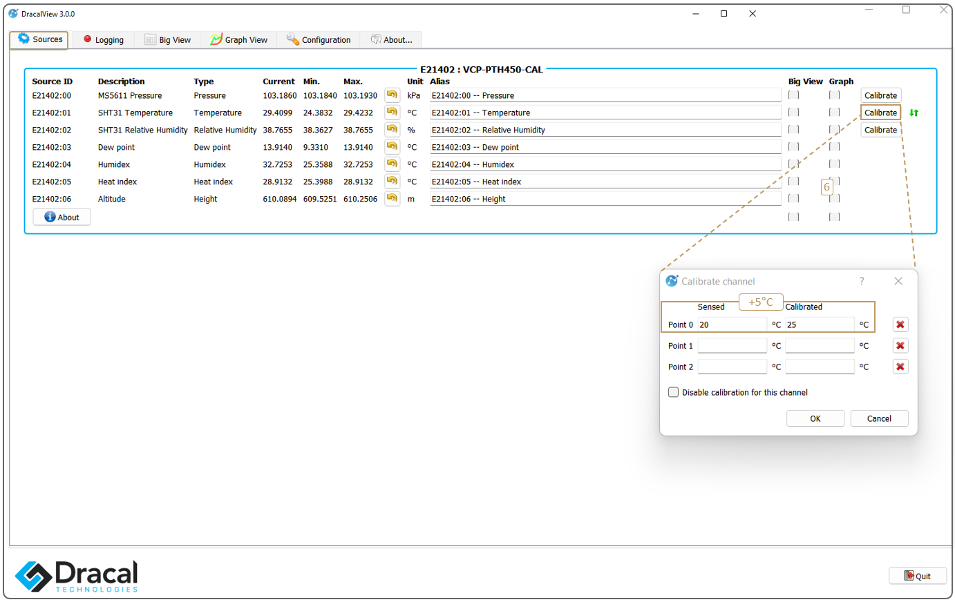
Let's see the effect of invoking the CAL OFF and CAL ON commands on the returned data:
C,VCP-PTH450-CAL,E21402,,103183,Pa,29.41,C,38.46,%,*d0ea
C,VCP-PTH450-CAL,E21402,,103183,Pa,29.40,C,38.46,%,*d39f
C,VCP-PTH450-CAL,E21402,,103182,Pa,29.41,C,38.48,%,*a746
I,VCP-PTH450-CAL,E21402,Calibration OFF,,,,,,,*6819       (Invoking command: CAL OFF)
D,VCP-PTH450-CAL,E21402,,103183,Pa,24.40,C,38.43,%,*b0a9
D,VCP-PTH450-CAL,E21402,,103183,Pa,24.41,C,38.49,%,*db77
D,VCP-PTH450-CAL,E21402,,103182,Pa,24.42,C,38.42,%,*1501
D,VCP-PTH450-CAL,E21402,,103184,Pa,24.41,C,38.46,%,*0619
I,VCP-PTH450-CAL,E21402,Calibration ON,,,,,,,*6819        (Invoking command: CAL ON)
C,VCP-PTH450-CAL,E21402,,103181,Pa,29.41,C,38.35,%,*972f
C,VCP-PTH450-CAL,E21402,,103181,Pa,29.41,C,38.34,%,*e19b
C,VCP-PTH450-CAL,E21402,,103181,Pa,29.40,C,38.31,%,*5eab
As expected, we can see that the temperature measurements in CAL ON mode, in orange, are indeed +5°C higher than the temperature data in CAL OFF mode, in green.
Note also the first element of the data lines, which indicate by the character C if the returned data are calibrated, and by the character D if they are not. In particular, a device in CAL ON mode for which no calibration point is entered will be identified by the letter D, as its data is effectively not calibrated.
6.4. Determine the number of decimal places to display: FRAC command
Sensors with both the VCP and CAL options are equipped with the FRAC command, which allows to choose the number of decimals to be displayed in VCP mode. The FRAC command can take integers from 1 to 7. Entering an integer greater than 7 is reduced to the upper limit of 7 decimal places.
Here is an illustration of the invocation of the FRAC command:
D,VCP-PTH450-CAL,E21402,,103180,Pa,24.3965050,C,38.4328960,%,*573b
D,VCP-PTH450-CAL,E21402,,103178,Pa,24.3965050,C,38.3489720,%,*9f9f
D,VCP-PTH450-CAL,E21402,,103179,Pa,24.4098570,C,38.3504980,%,*2e50
D,VCP-PTH450-CAL,E21402,,103178,Pa,24.3965050,C,38.3627050,%,*5599
I,VCP-PTH450-CAL,E21402,Printing 4 fractional digits,,,,,,,*70f1        (Invoking command: FRAC 4)
D,VCP-PTH450-CAL,E21402,,103180,Pa,24.4099,C,38.3780,%,*2af4
D,VCP-PTH450-CAL,E21402,,103181,Pa,24.3965,C,38.4192,%,*3ecf
D,VCP-PTH450-CAL,E21402,,103180,Pa,24.3832,C,38.3490,%,*213a
I,VCP-PTH450-CAL,E21402,Printing 2 fractional digits,,,,,,,*a9d4        (Invoking command: FRAC 2)
D,VCP-PTH450-CAL,E21402,,103183,Pa,24.40,C,38.42,%,*c61d
D,VCP-PTH450-CAL,E21402,,103181,Pa,24.38,C,38.43,%,*dac4
D,VCP-PTH450-CAL,E21402,,103179,Pa,24.41,C,38.42,%,*fe59
6.5. Convert back to USB mode: PROTOCOL and RESET commands
The command PROTOCOL is the one to be used to convert the communication protocol from VCP mode to USB mode. In order for the conversion to be effective, the device must then be disconnected either manually or virtually using the command RESET. Below is an example of the returned feedback after invocation of the commands PROTOCOL USB followed by RESET:
D,VCP-PTH200,E16026,,101671,Pa,23.2883,C,25.9022,%,*f065
D,VCP-PTH200,E16026,,101670,Pa,23.3017,C,25.7649,%,*ac59
D,VCP-PTH200,E16026,,101671,Pa,23.2883,C,25.5314,%,*a5a5
D,VCP-PTH200,E16026,,101669,Pa,23.3017,C,25.3696,%,*7c3c
I,VCP-PTH200,E16026,Protocol set,,,,,,,*0803                 (Invoking command: PROTOCOL USB)
D,VCP-PTH200,E16026,,101668,Pa,23.3017,C,25.2293,%,*3b0d
D,VCP-PTH200,E16026,,101669,Pa,23.315,C,25.1652,%,*89b9
D,VCP-PTH200,E16026,,101669,Pa,23.3017,C,25.1499,%,*F4371
D,VCP-PTH200,E16026,,101668,Pa,23.3017,C,25.1637,%,*6971
I,VCP-PTH200,E16026,Resetting device,,,,,,,*9500                (Invoking command: RESET)
At this point, your product communicates again via USB protocol and Windows users can access their data again via our free data acquisition software and tools. As for Linux and Mac OS X users, you have always been able to continue using these tools even when you were in VCP mode.